May 15, 2026
Blog

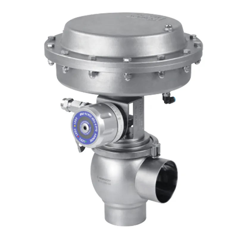
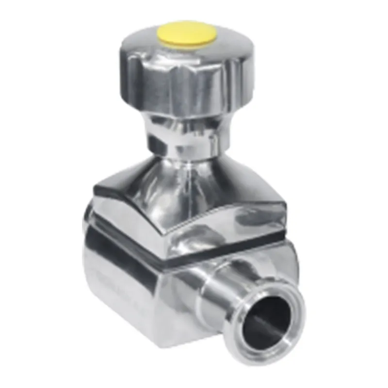
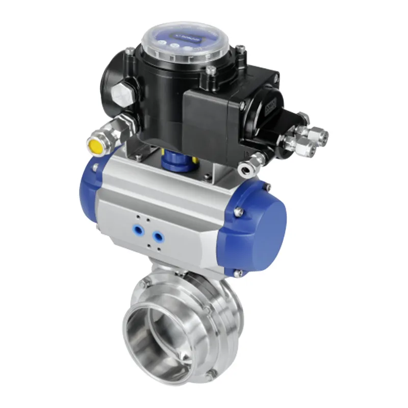
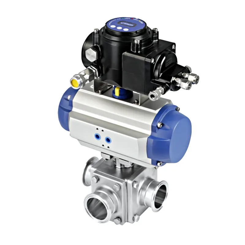
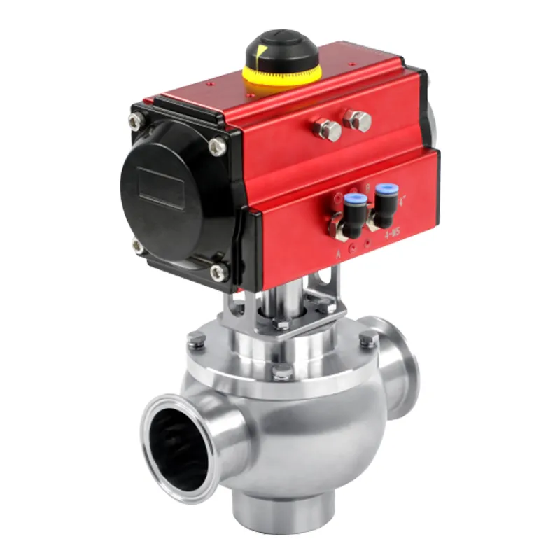
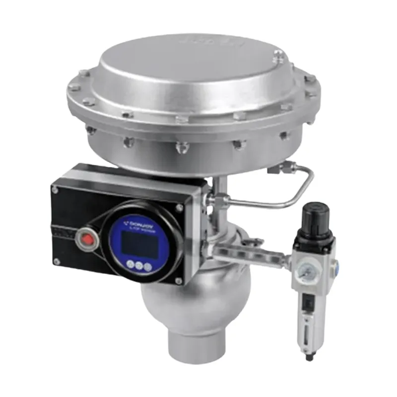
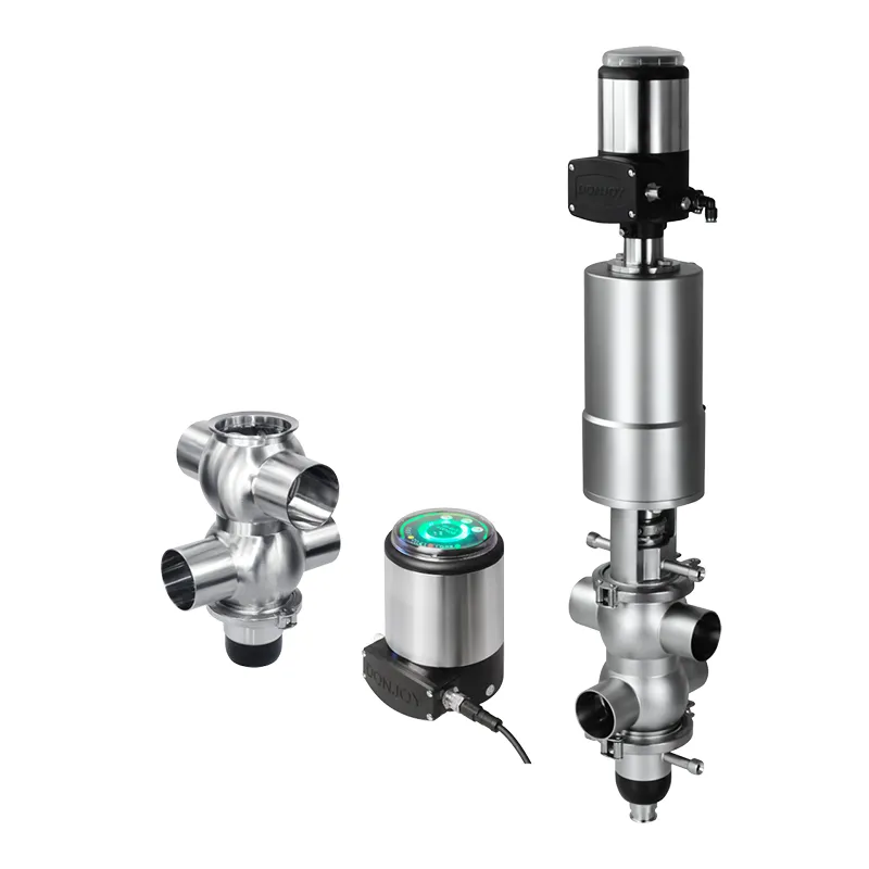
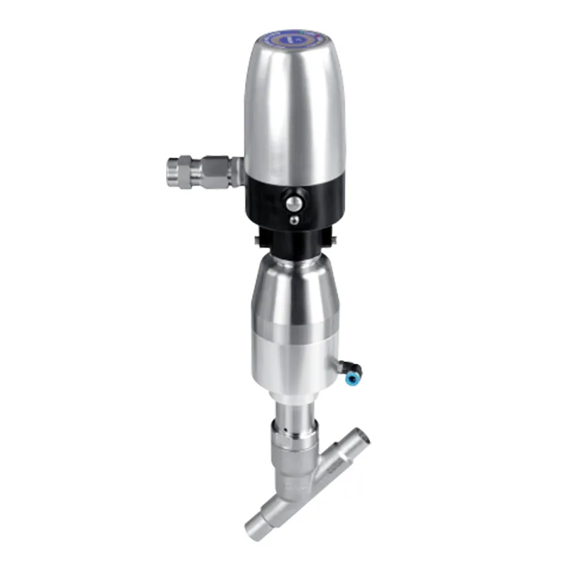
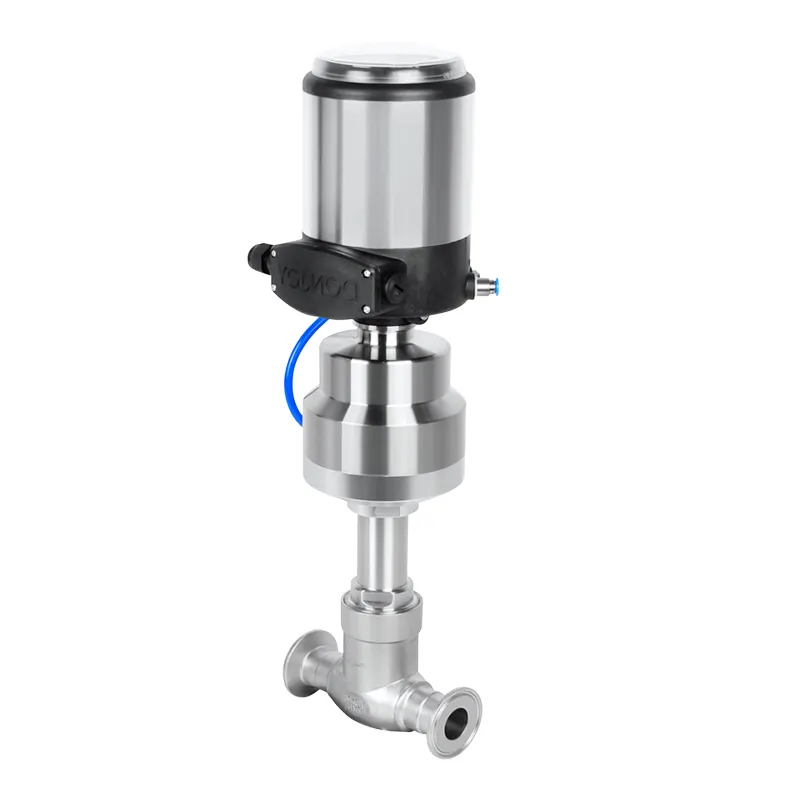
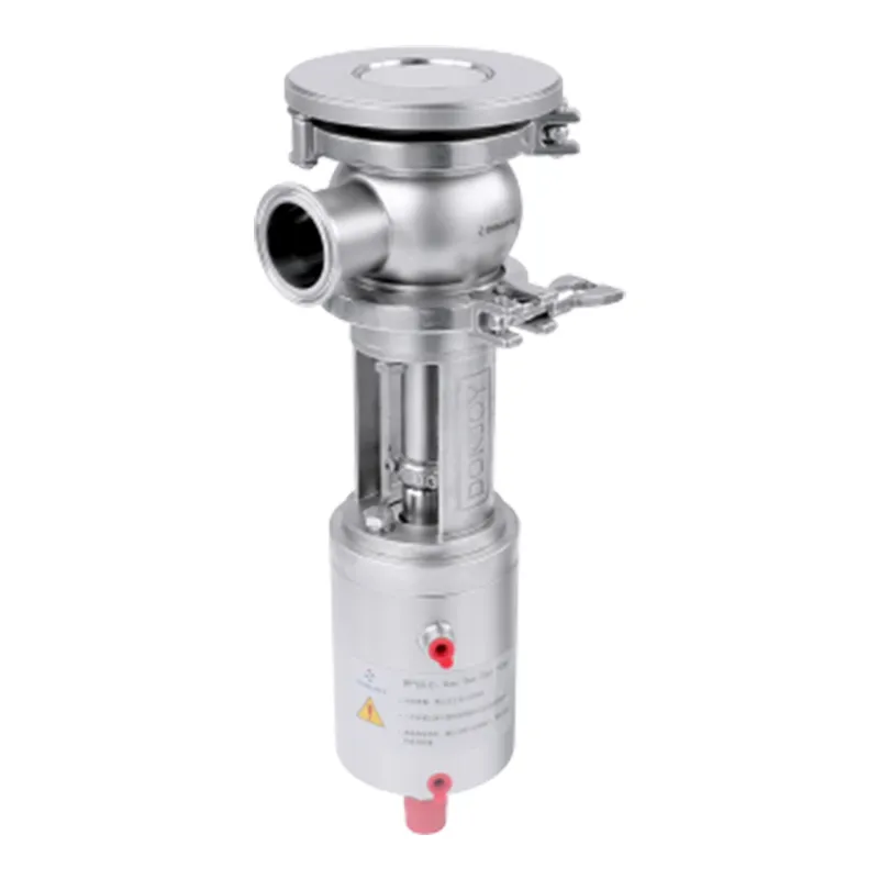
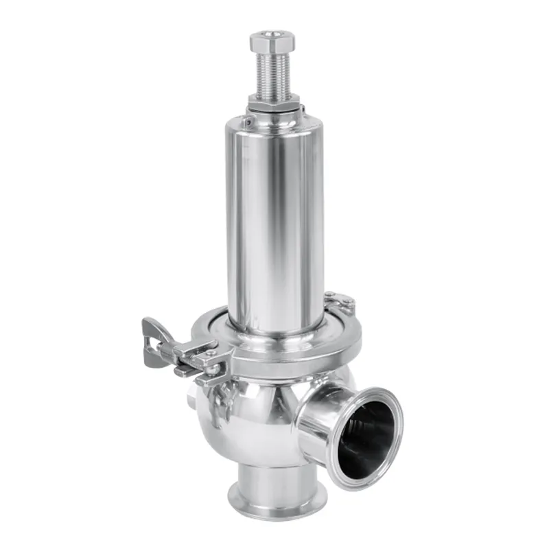
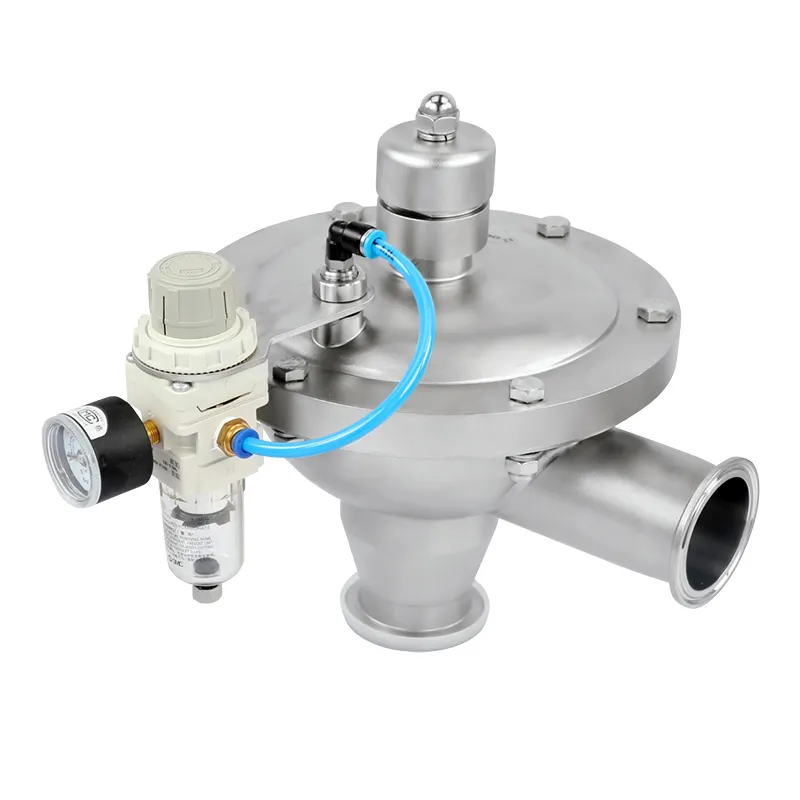
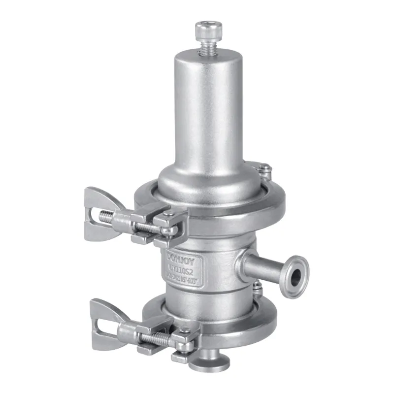
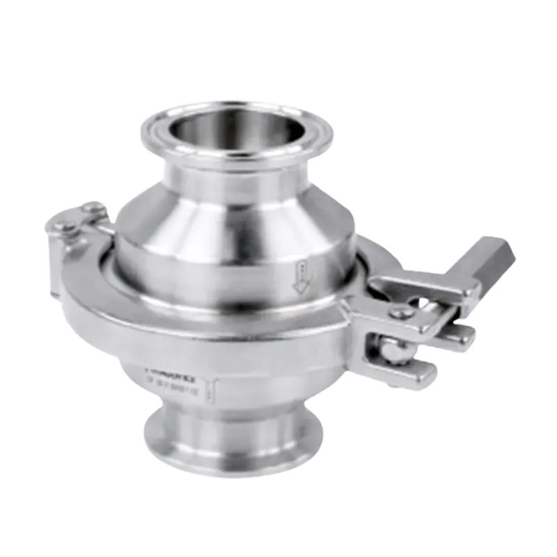
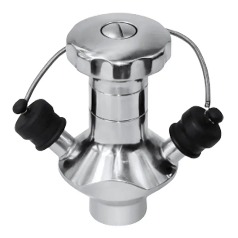
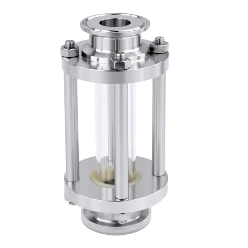
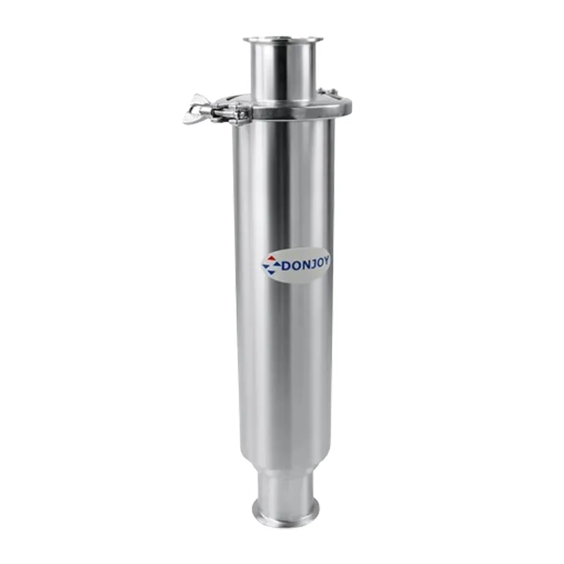
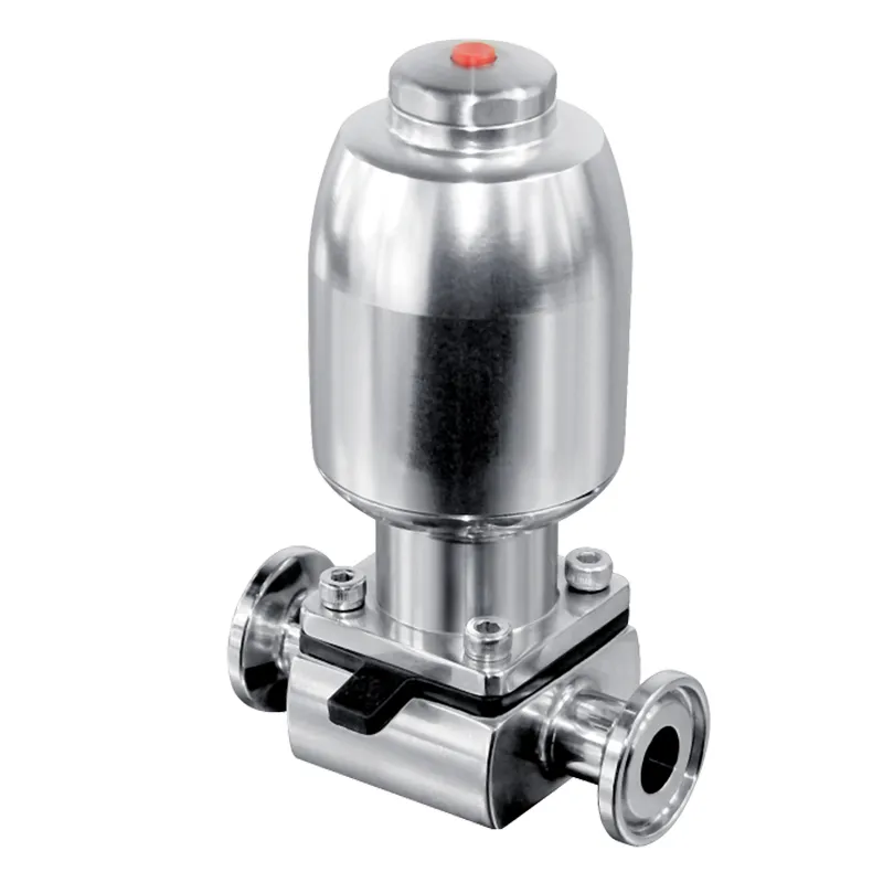
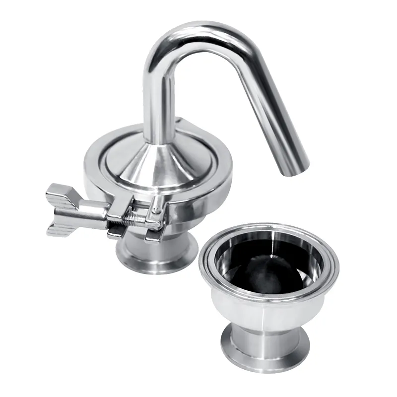
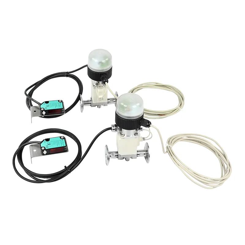
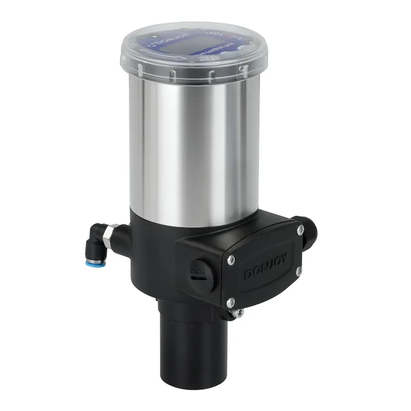
A sanitary check valve allows fluid to move in one direction while restricting reverse flow. It is commonly installed around pumps, tanks, filling equipment and hygienic processing lines where backflow could contaminate a product, disturb a process or allow a pipeline to drain unexpectedly.
Although the operating principle appears simple, check-valve performance depends on correct sizing and installation. Flow direction, mounting orientation, opening pressure, connection type and product properties can all influence whether the valve opens smoothly and closes reliably.
A valve installed in the wrong direction may block normal production completely. A valve with an unsuitable opening force may create unnecessary pressure loss or unstable movement. Selection should therefore be based on actual process conditions rather than pipe diameter alone.
A sanitary check valve contains a movable closure element that responds to the pressure difference between the upstream and downstream sides.
When upstream pressure is sufficient, the closure element moves away from the valve seat and allows forward flow.
When flow stops, upstream pressure falls or downstream pressure becomes higher, the closure element returns toward the seat and restricts reverse flow.
DONJOY’s sanitary check valve range includes center-clamped, three-piece, center-flanged, threaded, Y-type and mini check-valve configurations.
Unlike a manually operated isolation sanitary valve, a check valve normally operates automatically according to pressure conditions. It should not be treated as the only isolation device where positive shutoff is required for equipment maintenance.
The closure element, spring arrangement and internal body structure can vary between models. Buyers should review the specific drawing and technical data before selecting an installation orientation.
Correct check valve direction is normally indicated by an arrow on the valve body. The arrow must point in the intended direction of normal product flow.
Before completing check valve installation, verify:
The arrow on the valve body
The pipeline flow diagram
The position of the pump
The location of the vessel or equipment
The normal product-transfer direction
The CIP cleaning direction
Installing the valve backward can prevent normal forward flow. If a pump continues operating against an incorrectly installed check valve, pressure may build within the pipeline.
The correct check valve installation position depends on the internal design. Some spring-assisted valves can operate in several orientations, while gravity-dependent designs may have stricter installation requirements.
The installer should confirm:
Horizontal or vertical pipeline
Upward or downward fluid flow
Spring-assisted or gravity-assisted closure
Drainage after production
Drainage after CIP
Space for disassembly
Distance from pumps
Exposure to pulsation or vibration
A valve should not be installed in a particular orientation only because it fits the available space. Installation position can affect closure, drainage, cleaning and maintenance access.
For hygienic applications, the pipeline and valve should also be positioned to avoid unnecessary liquid retention after production or cleaning.
Check valve opening pressure, also called cracking pressure, is the upstream pressure difference required to begin moving the closure element away from the valve seat.
It is not the same as the valve’s maximum working-pressure rating.
Opening pressure describes when the valve begins to open. Maximum working pressure describes the allowable pressure limit of the valve body and its components.
If the opening pressure is too high, the pump may need to generate additional pressure before flow begins. This reduces the pressure available for the rest of the process system.
If the opening pressure is too low, the valve may move repeatedly when pipeline pressure fluctuates. This can contribute to unstable operation or valve chatter.
The required opening pressure should be selected according to:
Normal upstream pressure
Expected downstream pressure
Required flow rate
Pump operating conditions
Product viscosity
Installation orientation
Acceptable pressure loss
Frequency of pressure fluctuation
One opening-pressure value should not be applied to every check valve. The applicable value depends on the model, size, spring and closure structure.
Buyers should ask the supplier to confirm the opening pressure for the selected configuration rather than estimating it from another valve design.
Different check valve types are available to match piping standards, maintenance requirements and installation space.
A center-clamped check valve supports relatively fast disassembly and inspection. It is suitable for hygienic systems in which seals and internal components require regular examination.
A three-piece design allows the valve body to be separated into several components for maintenance. Buyers should confirm how much surrounding pipework must be removed before servicing.
A threaded check valve can fit compact piping arrangements, but the exact thread standard and hygienic suitability should be confirmed.
A flanged check valve provides a mechanically robust connection when the plant piping or project specification requires flanges.
A y type check valve uses an angled body arrangement. It may provide a different installation envelope and maintenance path compared with a straight-body model.
DONJOY’s sanitary check valve range includes:
Center-clamped check valves
Three-piece check valves
Center-flanged check valves
Threaded check valves
Y-type check valves
Mini check valves
The connection method should match the plant’s piping standard, maintenance strategy and cleaning requirements. A valve should not be selected only because its nominal size matches the pipeline.
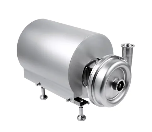
A check valve is commonly installed on the discharge side of a pump to prevent liquid from flowing backward when the pump stops.
When used with a sanitary centrifugal pump, the valve’s opening pressure and pressure loss must be included in the total system-head calculation.
Installing the check valve too close to a source of turbulence or pulsation may contribute to unstable movement. The pump and valve should therefore be evaluated as part of the complete piping system.
Valve chatter can occur when flow is too low, pressure fluctuates or the valve is oversized for the actual duty. Repeated movement may increase noise and wear on the closure element and seat.
Product particles can prevent the valve from seating correctly. When the process medium contains particles, the internal clearance and cleaning method should be reviewed before selection.
Incorrect orientation may slow closure or prevent complete drainage. This is particularly important in hygienic pipelines where residual product can affect cleaning results.
Common problems include:
| Problem | Possible Cause |
|---|---|
| No forward flow | Valve installed backward or insufficient upstream pressure |
| Reverse leakage | Damaged seat, trapped particles or seal wear |
| Valve chatter | Low flow, unstable pressure or oversized valve |
| Excessive pressure loss | Opening pressure too high or valve size unsuitable |
| Poor drainage | Incorrect installation orientation |
| Difficult cleaning | Product deposits or inadequate CIP flow |
Regular check valve maintenance should include inspection of:
Closure element
Valve seat
Sealing components
Spring, where applicable
Internal product deposits
Connection gaskets
Surface damage
Opening and closing movement
During troubleshooting, operators should first confirm the valve direction and available upstream pressure. Replacing the valve without identifying the process cause may not solve repeated chatter or leakage.
Some models can be installed horizontally, but suitability depends on the internal closure structure and the manufacturer’s installation guidance.
Yes, when the selected model supports the required upward or downward flow direction. Gravity and spring action must be considered.
A check valve is commonly installed on the pump discharge side to prevent reverse flow. The final location depends on the system design and pump requirements.
Possible causes include unstable pressure, insufficient flow, an oversized valve, pump pulsation or unsuitable opening pressure.
A hygienic check valve can be incorporated into a CIP system, but cleaning effectiveness depends on internal geometry, installation orientation, cleaning flow and temperature.
Provide the process medium, viscosity, particle content, required flow, pressure, temperature, installation orientation, required opening pressure, pipe size and connection standard.
Correct installation allows a sanitary check valve to open with minimal unnecessary resistance and close reliably when reverse pressure occurs. Reviewing the valve together with the pump, piping direction and cleaning system can reduce backflow risks and improve long-term operation.